SATA (Serial ATA) Interface Overview for SSD (Solid State Drives) and Modules
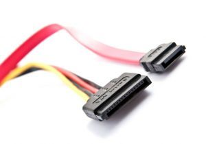
 SATA is a computer bus specifically for connecting mass storage devices to host systems. SATA stands for Serial ATA and is the follow-on interface to the PATA (Parallel ATA) interface originally designed in 1986.
The Serial ATA (SATA) interface was created in 2003 by the Serial ATA Working Group, which was later incorporated as a non-profit named the Serial ATA International Organization (SATA-IO).
The SATA interface was designed to be a much faster interface than PATA. Higher SATA speeds were arrived at by a much increased data rate on serial paired lines for transmit and receive.
The ATA/ATAPI basic interface commands used for the earlier PATA interface are supported by SATA to make the command set backward compatible.
A Brief History of the SATA Interface Revisions
| SATA VERSION | MAXIMUM PERFORMANCE | HIGHLIGHTED FEATURES |
|---|---|---|
| REVISION 1.0 (2003) |
1.5 GBITS/SEC (150 MBYTES/SEC) |
INITIAL SATA LAUNCH |
| REVISION 2.0 (2004) |
3.0 GBITS/SEC (300 MBYTES/SEC) |
BACKWARD COMPATIBLE WITH SATA 1.5 GBITS/SEC |
| REVISIONS 2.5/2.6 (2005/2007) |
3.0 GBITS/SEC (300 MBYTES/SEC) |
NCQ (NATIVE COMMAND QUEUING SLIMLINE/MICRO CABLES & CONNECTORS |
| REVISION 3.0 (2009) |
6.0 GBITS/SEC (600 MBYTES/SEC) |
BACKWARD COMPATIBLE WITH SATA 3.0 GBITS/SEC |
| REVISION 3.1 (2011) |
6.0 GBITS/SEC (600 MBYTES/SEC) |
MSATA (MO-300) DEFINED TRIM COMMAND |
| REVISION 3.2 (2013) |
16 GBITS/SEC (1969 MBYTES/SEC) |
M.2 (NGFF) DEFINED SATA EXPRESS SPEC |
2.5" SATA SSD and Slim SATA (MO-297) Connector

The contact pads for these products is only found on one side of the connector. As you can see by the image, some pads are longer so they will make contact sooner when the connector is inserted. This is done to make sure the devices start up properly when hot swapping.
The detailed signal breakdown as used on the Cactus Industrial Grade SATA SSD are shown in the table below.
| PIN NUMBER | ASSIGNMENT | DESCRIPTION |
|---|---|---|
| S1 - DATA | GROUND | FIRST TO CONTACT |
| S2 - DATA | A+ | HOST (TRANSMIT +) |
| S3 - DATA | A- | HOST (TRANSMIT -) |
| S4 - DATA | GROUND | FIRST TO CONTACT |
| S5 - DATA | B- | HOST (RECEIVE -) |
| S6 - DATA | B+ | HOST (RECEIVE +) |
| S7 - DATA | GROUND | FIRST TO CONTACT |
| CODING NOTCH | KEYS THE CONNECTOR | |
| P1 - POWER | +3.3 V | 3.3 V SOURCE |
| P2 - POWER | +3.3 V | 3.3 V SOURCE |
| P3 - POWER | +3.3 V | 3.3 V SOURCE |
| P4 - POWER | GROUND | FIRST TO CONTACT |
| P5 - POWER | GROUND | FIRST TO CONTACT |
| P6 - POWER | GROUND | FIRST TO CONTACT |
| P7 - POWER | +5.0 V | 5.0 V SUPPLY |
| P8 - POWER | +5.0 V | 5.0 V SOURCE |
| P9 - POWER | +5.0 V | 5.0 V SOURCE |
| P10 - POWER | GROUND | FIRST TO CONTACT |
| P11 - POWER | ACTIVE LED | ACTIVITY LED |
| P12 - POWER | GROUND | FIRST TO CONTACT |
| P13 - POWER | +12.0 V | 12.0 V SOURCE |
| P14 - POWER | +12.0 V | 12.0 V SOURCE |
| P15 - POWER | +12.0 V | 12.0 V SOURCE |
mSATA (MO-300) Connector

Below is a detailed signal breakdown as used on the Cactus Industrial Grade mSATA SSD.
| PIN # | ASSIGNMENT | DESCRIPTION | PIN # | ASSIGNMENT | DESCRIPTION |
|---|---|---|---|---|---|
| 1 | N/A | N/A | 27 | GROUND | RETURN CURRENT PATH |
| 2 | +3.3 V | 3.3 V SOURCE | 28 | N/A | N/A |
| 3 | N/A | N/A | 29 | GROUND | RETURN CURRENT PATH |
| 4 | GROUND | RETURN CURRENT PATH | 30 | N/A | N/A |
| 5 | N/A | N/A | 31 | RX- | SATA DIFFERENTIAL |
| 6 | N/A | N/A | 32 | N/A | N/A |
| 7 | N/A | N/A | 33 | RX+ | SATA DIFFERENTIAL |
| 8 | N/A | N/A | 34 | GROUND | RETURN CURRENT PATH |
| 9 | GROUND | RETURN CURRENT PATH | 35 | GROUND | RETURN CURRENT PATH |
| 10 | N/A | N/A | 36 | RESERVED | NO CONNECT |
| 11 | N/A | N/A | 37 | GROUND | RETURN CURRENT PATH |
| 12 | N/A | N/A | 38 | RESERVED | NO CONNECT |
| 13 | N/A | N/A | 39 | +3.3 V | 3.3 V SOURCE |
| 14 | N/A | N/A | 40 | GROUND | RETURN CURRENT PATH |
| 15 | GROUND | RETURN CURRENT PATH | 41 | +3.3 V | 3.3 V SOURCE |
| 16 | N/A | N/A | 42 | N/A | N/A |
| 17 | N/A | N/A | 43 | GROUND | RETURN CURRENT PATH |
| 18 | GROUND | RETURN CURRENT PATH | 44 | N/A | N/A |
| 19 | N/A | N/A | 45 | RESERVED | N/A |
| 20 | N/A | N/A | 46 | N/A | N/A |
| 21 | GROUND | RETURN CURRENT PATH | 47 | RESERVED | N/A |
| 22 | N/A | N/A | 48 | N/A | N/A |
| 23 | TX+ | SATA DIFFERENTIAL | 49 | DA/DSS | DEVICE ACTIVITY/DISABLE STAGGERED SPIN UP |
| 24 | +3.3 V | 3.3 V SOURCE | 50 | GROUND | RETURN CURRENT PATH |
| 25 | TX- | SATA DIFFERENTIAL | 51 | PRESENCE DETECTION | PULLED TO GROUND BY DEVICE |
| 26 | GROUND | RETURN CURRENT PATH | 52 | +3.3 V | 3.3 V SOURCE |
Other SATA Modules
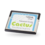
 To round out the Cactus SATA interface offering, we have CFast products which are defined by the CompactFlash Association and possibly a future M.2 (NGFF) form factor.
Cactus offers both an Industrial Grade CFast and MLC CFast card to meet different OEM market requirements. I will provide more details on these parts in another post.
As always, if you need more information on the Cactus products to assist with a design, Talk to a Cactus Expert.


